Using Scale Factors Sx and Sy for X and Y Again
This browser is no longer supported.
Upgrade to Microsoft Edge to take advantage of the latest features, security updates, and technical support.
The Scale Transform
 Download the sample
Discover the SkiaSharp scale transform for scaling objects to various sizes
As you've seen in The Translate Transform article, the interpret transform can move a graphical object from one location to another. In contrast, the scale transform changes the size of the graphical object:
The scale transform also oftentimes causes graphics coordinates to motion as they are made larger.
Before yous saw two transform formulas that describe the effects of translation factors of dx and dy:
x' = 10 + dx
y' = y + dy
Scale factors of sx and sy are multiplicative rather than additive:
x' = sx · ten
y' = sy · y
The default values of the translate factors are 0; the default values of the scale factors are 1.
The SKCanvas form defines 4 Scale methods. The start Scale method is for cases when you want the aforementioned horizontal and vertical scaling cistron:
public void Scale (Single southward) This is known as isotropic scaling — scaling that is the same in both directions. Isotropic scaling preserves the object'due south aspect ratio.
The 2d Scale method lets you specify unlike values for horizontal and vertical scaling:
public void Scale (Unmarried sx, Single sy) This results in anisotropic scaling. The third Scale method combines the two scaling factors in a single SKPoint value:
public void Scale (SKPoint size) The fourth Scale method will be described shortly.
The Basic Calibration page demonstrates the Scale method. The BasicScalePage.xaml file contains two Slider elements that let you select horizontal and vertical scaling factors betwixt 0 and 10. The BasicScalePage.xaml.cs code-behind file uses those values to call Scale earlier displaying a rounded rectangle stroked with a dashed line and sized to fit some text in the upper-left corner of the canvas:
void OnCanvasViewPaintSurface(object sender, SKPaintSurfaceEventArgs args) { SKImageInfo info = args.Info; SKSurface surface = args.Surface; SKCanvas canvas = surface.Canvas; sheet.Clear(SKColors.SkyBlue); using (SKPaint strokePaint = new SKPaint { Style = SKPaintStyle.Stroke, Color = SKColors.Blood-red, StrokeWidth = iii, PathEffect = SKPathEffect.CreateDash(new float[] { 7, seven }, 0) }) using (SKPaint textPaint = new SKPaint { Style = SKPaintStyle.Fill, Color = SKColors.Blueish, TextSize = 50 }) { canvas.Calibration((float)xScaleSlider.Value, (float)yScaleSlider.Value); SKRect textBounds = new SKRect(); textPaint.MeasureText(Title, ref textBounds); float margin = 10; SKRect borderRect = SKRect.Create(new SKPoint(margin, margin), textBounds.Size); canvas.DrawRoundRect(borderRect, twenty, 20, strokePaint); canvas.DrawText(Championship, margin, -textBounds.Top + margin, textPaint); } } Yous might wonder: How exercise the scaling factors affect the value returned from the MeasureText method of SKPaint? The answer is: Non at all. Scale is a method of SKCanvas. It does non affect anything you do with an SKPaint object until you employ that object to render something on the canvas.
As you can run into, everything drawn subsequently the Scale telephone call increases proportionally:

The text, the width of the dashed line, the length of the dashes in that line, the rounding of the corners, and the 10-pixel margin betwixt the left and top edges of the canvass and the rounded rectangle are all subject field to the same scaling factors.
Important
The Universal Windows Platform does non properly render anisotropicly scaled text.
Anisotropic scaling causes the stroke width to get different for lines aligned with the horizontal and vertical axes. (This is also evident from the first prototype on this page.) If you don't want the stroke width to be afflicted past the scaling factors, set it to 0 and it will always exist ane pixel wide regardless of the Scale setting.
Scaling is relative to the upper-left corner of the canvass. This might be exactly what you want, but it might not be. Suppose y'all want to position the text and rectangle somewhere else on the canvas and you want to calibration it relative to its centre. In that instance you lot can use the fourth version of the Scale method, which includes two boosted parameters to specify the heart of scaling:
public void Scale (Single sx, Single sy, Single px, Single py) The px and py parameters define a bespeak that is sometimes chosen the scaling center but in the SkiaSharp documentation is referred to equally a pivot signal. This is a point relative to the upper-left corner of the canvass that is not affected by the scaling. All scaling occurs relative to that centre.
The Centered Scale page shows how this works. The PaintSurface handler is similar to the Basic Scale programme except that the margin value is calculated to center the text horizontally, which implies that the program works best in portrait mode:
void OnCanvasViewPaintSurface(object sender, SKPaintSurfaceEventArgs args) { SKImageInfo info = args.Info; SKSurface surface = args.Surface; SKCanvas canvass = surface.Sail; canvass.Clear(SKColors.SkyBlue); using (SKPaint strokePaint = new SKPaint { Manner = SKPaintStyle.Stroke, Colour = SKColors.Red, StrokeWidth = 3, PathEffect = SKPathEffect.CreateDash(new float[] { 7, 7 }, 0) }) using (SKPaint textPaint = new SKPaint { Style = SKPaintStyle.Fill, Colour = SKColors.Bluish, TextSize = l }) { SKRect textBounds = new SKRect(); textPaint.MeasureText(Title, ref textBounds); float margin = (info.Width - textBounds.Width) / 2; float sx = (bladder)xScaleSlider.Value; bladder sy = (float)yScaleSlider.Value; float px = margin + textBounds.Width / 2; float py = margin + textBounds.Peak / 2; sail.Scale(sx, sy, px, py); SKRect borderRect = SKRect.Create(new SKPoint(margin, margin), textBounds.Size); canvas.DrawRoundRect(borderRect, 20, twenty, strokePaint); canvass.DrawText(Title, margin, -textBounds.Top + margin, textPaint); } } The upper-left corner of the rounded rectangle is positioned margin pixels from the left of the canvas and margin pixels from the summit. The last two arguments to the Scale method are set to those values plus the width and height of the text, which is also the width and peak of the rounded rectangle. This means that all scaling is relative to the heart of that rectangle:
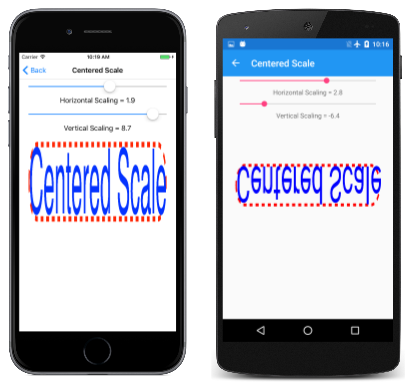
The Slider elements in this program have a range of –x to x. As y'all can see, negative values of vertical scaling (such as on the Android screen in the center) cause objects to flip effectually the horizontal axis that passes through the center of scaling. Negative values of horizontal scaling (such every bit in the UWP screen on the correct) cause objects to flip around the vertical axis that passes through the middle of scaling.
The version of the Calibration method with pin points is a shortcut for a series of iii Translate and Scale calls. You might desire to see how this works by replacing the Scale method in the Centered Calibration page with the following:
canvas.Translate(-px, -py); These are the negatives of the pin point coordinates.
Now run the program again. Y'all'll see that the rectangle and text are shifted then that the center is in the upper-left corner of the canvas. Y'all tin barely see it. The sliders don't work of course because now the plan doesn't calibration at all.
Now add the basic Scale phone call (without a scaling center) earlier that Translate phone call:
sheet.Scale(sx, sy); canvas.Translate(–px, –py); If yous're familiar with this do in other graphics programming systems, yous might think that's wrong, simply information technology'due south non. Skia handles successive transform calls a fiddling differently from what you lot might be familiar with.
With the successive Scale and Translate calls, the center of the rounded rectangle is still in the upper-left corner, just you lot can at present calibration information technology relative to the upper-left corner of the sail, which is likewise the center of the rounded rectangle.
Now, before that Scale phone call, add some other Translate call with the centering values:
canvas.Translate(px, py); canvas.Scale(sx, sy); sheet.Translate(–px, –py); This moves the scaled result back to the original position. Those iii calls are equivalent to:
canvas.Scale(sx, sy, px, py); The individual transforms are compounded so that the total transform formula is:
x' = sx · (x – px) + px
y' = sy · (y – py) + py
Keep in mind that the default values of sx and sy are 1. It'southward like shooting fish in a barrel to convince yourself that the pivot point (px, py) is non transformed by these formulas. It remains in the same location relative to the canvas.
When you lot combine Interpret and Scale calls, the social club matters. If the Translate comes after the Scale, the translation factors are effectively scaled by the scaling factors. If the Translate comes earlier the Scale, the translation factors are not scaled. This process becomes somewhat clearer (albeit more mathematical) when the subject area of transform matrices is introduced.
The SKPath course defines a read-only Premises belongings that returns an SKRect defining the extent of the coordinates in the path. For example, when the Bounds property is obtained from the hendecagram path created earlier, the Left and Superlative properties of the rectangle are approximately –100, the Right and Bottom properties are approximately 100, and the Width and Height properties are approximately 200. (Most of the actual values are a petty less considering the points of the stars are defined by a circle with a radius of 100 just but the top betoken is parallel with the horizontal or vertical axes.)
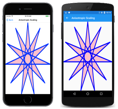
The availability of this information implies that information technology should be possible to derive scale and translate factors suitable for scaling a path to the size of the sail. The Anisotropic Scaling page demonstrates this with the 11-pointed star. An anisotropic scale means that information technology'due south unequal in the horizontal and vertical directions, which ways that the star won't retain its original aspect ratio. Hither'south the relevant code in the PaintSurface handler:
SKPath path = HendecagramPage.HendecagramPath; SKRect pathBounds = path.Bounds; using (SKPaint fillPaint = new SKPaint { Manner = SKPaintStyle.Fill, Color = SKColors.Pink }) using (SKPaint strokePaint = new SKPaint { Style = SKPaintStyle.Stroke, Color = SKColors.Bluish, StrokeWidth = three, StrokeJoin = SKStrokeJoin.Round }) { sheet.Scale(info.Width / pathBounds.Width, info.Acme / pathBounds.Height); canvas.Translate(-pathBounds.Left, -pathBounds.Height); sheet.DrawPath(path, fillPaint); canvas.DrawPath(path, strokePaint); } The pathBounds rectangle is obtained near the elevation of this code, and and then used afterward with the width and acme of the canvas in the Scale call. That call by itself volition scale the coordinates of the path when it's rendered by the DrawPath call but the star will exist centered in the upper-right corner of the canvas. It needs to be shifted down and to the left. This is the job of the Interpret call. Those two properties of pathBounds are approximately –100, then the translation factors are about 100. Because the Translate phone call is after the Scale telephone call, those values are finer scaled by the scaling factors, so they move the center of the star to the centre of the canvass:
Another style you can recall about the Scale and Translate calls is to decide the outcome in reverse sequence: The Translate phone call shifts the path and then it becomes fully visible but oriented in the upper-left corner of the canvas. The Scale method and then makes that star larger relative to the upper-left corner.
Actually, it appears that the star is a little larger than the canvas. The problem is the stroke width. The Bounds property of SKPath indicates the dimensions of the coordinates encoded in the path, and that's what the plan uses to calibration it. When the path is rendered with a particular stroke width, the rendered path is larger than the sheet.
To prepare this problem you need to compensate for that. One easy approach in this program is to add the following statement right earlier the Scale call:
pathBounds.Inflate(strokePaint.StrokeWidth / 2, strokePaint.StrokeWidth / ii); This increases the pathBounds rectangle by ane.5 units on all four sides. This is a reasonable solution but when the stroke join is rounded. A miter join can be longer and is hard to calculate.
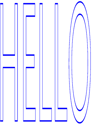
You can also use a like technique with text, as the Anisotropic Text folio demonstrates. Here's the relevant role of the PaintSurface handler from the AnisotropicTextPage grade:
using (SKPaint textPaint = new SKPaint { Fashion = SKPaintStyle.Stroke, Color = SKColors.Blue, StrokeWidth = 0.1f, StrokeJoin = SKStrokeJoin.Circular }) { SKRect textBounds = new SKRect(); textPaint.MeasureText("HELLO", ref textBounds); // Inflate premises by the stroke width textBounds.Inflate(textPaint.StrokeWidth / 2, textPaint.StrokeWidth / two); canvas.Scale(info.Width / textBounds.Width, info.Summit / textBounds.Height); canvas.Interpret(-textBounds.Left, -textBounds.Pinnacle); canvas.DrawText("HELLO", 0, 0, textPaint); } Information technology's similar logic, and the text expands to the size of the page based on the text bounds rectangle returned from MeasureText (which is a little larger than the bodily text):

If you demand to preserve the aspect ratio of the graphical objects, yous'll want to use isotropic scaling. The Isotropic Scaling folio demonstrates this for the eleven-pointed star. Conceptually, the steps for displaying a graphical object in the middle of the folio with isotropic scaling are:
- Translate the center of the graphical object to the upper-left corner.
- Scale the object based on the minimum of the horizontal and vertical page dimensions divided by the graphical object dimensions.
- Translate the heart of the scaled object to the center of the page.
The IsotropicScalingPage performs these steps in opposite order before displaying the star:
void OnCanvasViewPaintSurface(object sender, SKPaintSurfaceEventArgs args) { SKImageInfo info = args.Info; SKSurface surface = args.Surface; SKCanvas canvas = surface.Canvas; sheet.Clear(); SKPath path = HendecagramArrayPage.HendecagramPath; SKRect pathBounds = path.Premises; using (SKPaint fillPaint = new SKPaint()) { fillPaint.Manner = SKPaintStyle.Fill up; float scale = Math.Min(info.Width / pathBounds.Width, info.Height / pathBounds.Acme); for (int i = 0; i <= 10; i++) { fillPaint.Color = new SKColor((byte)(255 * (10 - i) / 10), 0, (byte)(255 * i / 10)); sail.Salve(); sheet.Translate(info.Width / 2, info.Peak / 2); sail.Scale(scale); canvass.Interpret(-pathBounds.MidX, -pathBounds.MidY); canvas.DrawPath(path, fillPaint); canvas.Restore(); calibration *= 0.9f; } } } The code likewise displays the star 10 more times, each time decreasing the scaling factor past 10% and progressively irresolute the color from red to blue:

- SkiaSharp APIs
- SkiaSharpFormsDemos (sample)
Feedback
Submit and view feedback for
Source: https://docs.microsoft.com/en-us/xamarin/xamarin-forms/user-interface/graphics/skiasharp/transforms/scale
0 Response to "Using Scale Factors Sx and Sy for X and Y Again"
Enviar um comentário